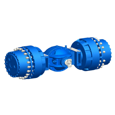
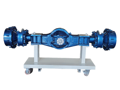
Structure of the Drive Axle
The drive axle is composed of the final drive, differential, half shafts, and axle housing. Its functions are:
① Transmitting the engine torque from the universal transmission device to the drive wheels through the final drive, differential, half shafts, etc., to achieve speed reduction and torque increase;
② Changing the transmission direction of torque through the bevel gear pair of the final drive;
③ Realizing the differential action of the two side wheels through the differential to ensure that the inner and outer wheels steer at different rotational speeds.

Steering drive axles also have constant-velocity joints. In addition, the drive axle must bear the vertical forces, longitudinal forces, lateral forces, and reaction forces acting between the road surface and the frame or body.
1. The function of the final drive is to increase the input torque and correspondingly reduce the rotational speed, and when the engine is longitudinally mounted, it also changes the direction of torque rotation. There are many types of final drives, including single-stage, two-stage, two-speed, wheel-side reducers, etc.
1.1 Single-stage final drive
A device that achieves speed reduction through a pair of speed-reducing gears is called a single-stage final drive. It has the advantages of simple structure, small size, light weight, and high efficiency.
1.2 Two-stage final drive
When the engine characteristics and vehicle operating conditions require the final drive to have a larger gear ratio, a single-stage final drive composed of a pair of bevel gears can no longer ensure sufficient ground clearance. In this case, a two-stage final drive using two pairs of gears for speed reduction is required.
1.3 Wheel-end Reducer
In heavy-duty trucks, off-road vehicles, and large buses, when a larger main gear ratio and a larger ground clearance are required, the second-stage reduction gear mechanism in the two-stage main reducer is often manufactured into two identical sets, which are respectively installed adjacent to the driving wheels on both sides. These are referred to as wheel-end reducers, while the first stage is called the main reducer.
2. The differential is used to connect the left and right half shafts, allowing the two wheels to rotate at different angular velocities while transmitting torque, ensuring the normal rolling of the wheels. In some multi-axle drive vehicles, differentials are also installed within the transfer case or between axles in through-type drives, referred to as inter-axle differentials. Their function is to create a differential effect between the front and rear drive wheels when the vehicle turns or travels on uneven roads.
3. The half shaft is a solid shaft that transmits the torque from the differential to the wheels, driving them to rotate and propelling the vehicle. Due to different installation structures of the wheel hub, the force conditions of the half shaft vary. Therefore, half shafts are classified into three types: full-floating type, semi-floating type, and three-quarter floating type.
3.1 Full-Floating Half Shaft
Full-floating structures are generally used in large and medium-sized vehicles. The inner end of the half shaft is connected to the half shaft gear of the differential via splines, while the outer end is forged with a flange and connected to the wheel hub using bolts. The wheel hub is supported on the half shaft casing by two widely spaced tapered roller bearings. The half shaft casing is press-fitted with the rear axle housing to form the drive axle housing. With this type of support, the half shaft has no direct connection to the axle housing, meaning the half shaft only bears driving torque without any bending moment. This type of half shaft is called a "full-floating" half shaft.
3.2 Semi-Floating Half Shaft
The inner end of the semi-floating half shaft is the same as that of the full-floating type, not bearing bending or twisting forces. Its outer end is directly supported on the inner side of the half shaft housing via a single bearing. This support method causes the outer end of the half shaft to bear bending moments. Therefore, in addition to transmitting torque, this type of half shaft partially bears bending moments, hence it is called a semi-floating half shaft. This structural type is mainly used in passenger cars.
3.3 Three-Quarter Floating Half Shaft
The degree to which the three-quarter floating half shaft withstands bending moments lies between that of the semi-floating and full-floating types. This type of half shaft is not widely used, only applied in individual passenger cars.

4. Axle Housing
4.1 Integral Axle Housing
Integral axle housings are widely used due to their good strength and stiffness properties, as well as ease of installation, adjustment, and maintenance of the main reducer. Depending on the manufacturing method, integral axle housings can be divided into monoblock casting type, central casting with pressed-in steel tube type, and stamped and welded steel plate type, etc.
4.2 Segmented Drive Axle Housing
Segmented drive axle housings are generally divided into two segments, which are connected into one piece by bolts. Segmented axle housings are relatively easy to cast and machine.